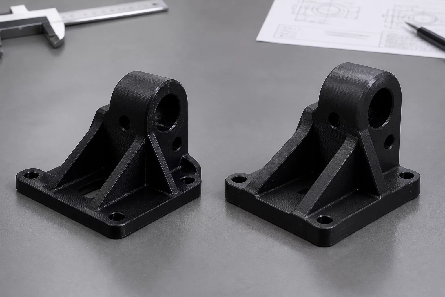
The transition from the initial prototype (V1) to the reinforced version (V2) highlights the critical importance of internal structure in fused deposition modeling. Version 1 was designed primarily to verify fitment and mounting hole positions. It utilized a standard 2-wall shell and 15% grid infill. While this resulted in a fast print time, the part failed during stress testing when the mounting arm buckled under a 5kg load. The failure was characterized by a clean shear along the layer lines, suggesting that the bonding surface was insufficient for the mechanical demands.
For Version 2, the design team focused on optimizing the slicing parameters without significantly increasing the weight of the part. We doubled the outer wall count to four layers and switched the infill pattern to a 25% gyroid configuration. Unlike the linear grid pattern, the gyroid structure provides isotropic strength, resisting forces from multiple directions simultaneously. Furthermore, a 5mm fillet was added to the interior 90-degree angle to eliminate stress concentrators that were present in the sharper V1 geometry. The result was a significantly more robust part that successfully withstood loads up to 25kg before showing signs of fatigue.
Technical Iteration Analysis
Verdict & Performance Results
The iteration from V1 to V2 achieved a 400% increase in structural load capacity while increasing total material usage by only 22%. The functional verification confirms that V2 is suitable for production use in the chassis assembly. By documenting these changes, we have established a standard profile for similar mechanical brackets within the project ecosystem.